Using PID (Proportional-Integral-Derivative) controller with AC Drive or VFD (Variable Frequency Drive) is common and highly beneficial when controlling pumps or fans for energy savings.
Here’s why:
▪️ Stable & Precise Control
▪️ Minimizes energy consumption by reducing the need for the system to run at full capacity continuously.
▪️ Maintain consistent pressure or flow in the system, leading to smoother operation which reduces potential wear and tear on the equipment.
Drive Built in PID Controller offer additional advantage such as:
▪️ Reduces wiring & simplify the system design
▪️ Reduce cost
▪️ Save panel spaces
▪️ Easier to set up & configure
Even not as flexible & customizable as PID Controller in PLC , it is quicker & simpler for basic PID control needs.
What Hardware that needed?
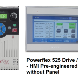
1️⃣ Powerflex 525 Drive. The Drive has:
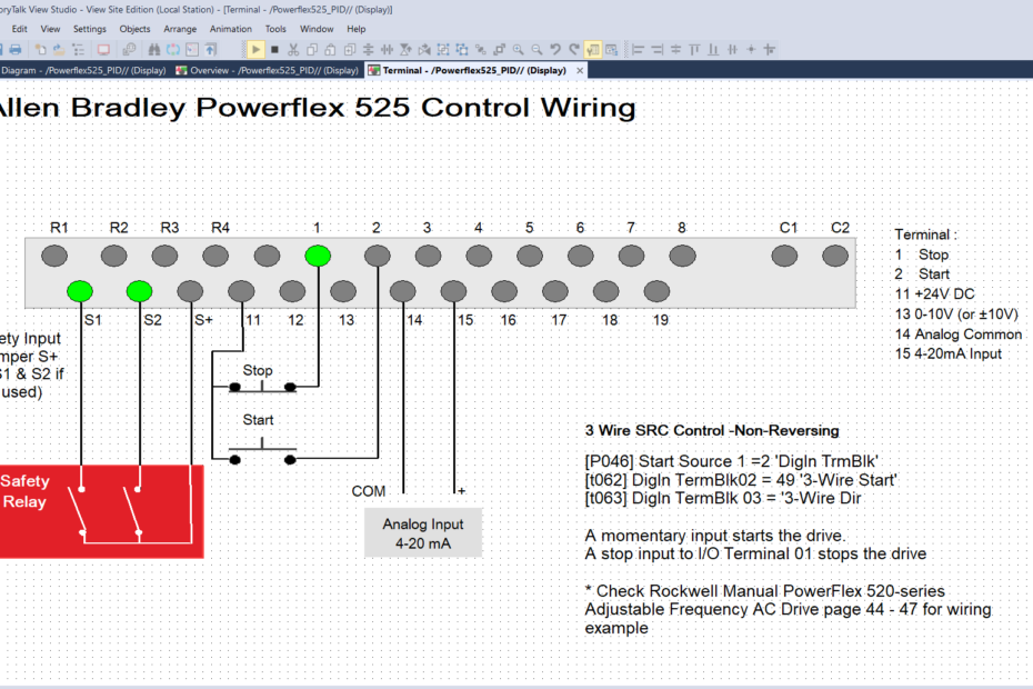
– Isolated 4-20 & 0-10VDC Analog input to receive signal from Field Instrument (Level, Flow, Pressure etc)
– Digital I/O for Start & Stop.
– Safety Torque Off (STO) to connect to Emergency Stop Line
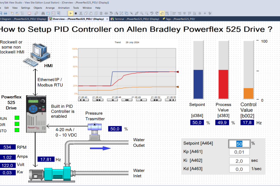
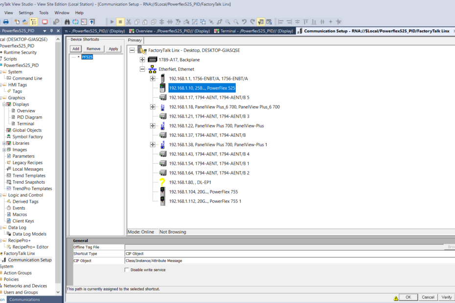
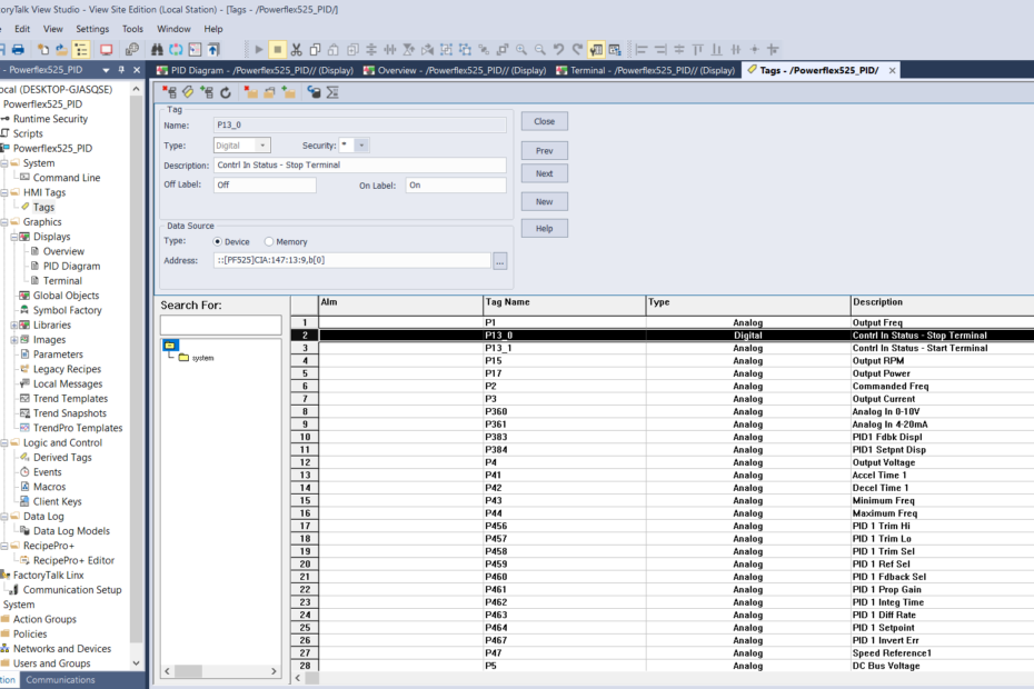
2️⃣ Optional HMI with Modbus RTU or Explicit Ethernet/IP Driver, for setting PID Setpoint, monitor & set Drive PID parameter.
Here’s about PID Controller at Powerflex 525 Drive:
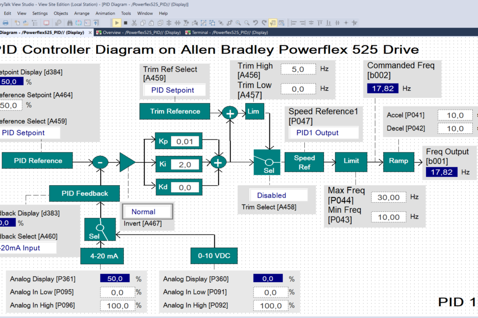
▪️ Loop update time is 1 milli second
▪️ PID Controller can be set as;
– Speed Trim = The PID Output added to the master speed reference
– Exclusive Control = PID have exclusive control of the commanded speed
▪️ Built in 2 PID Loops
How to setup?
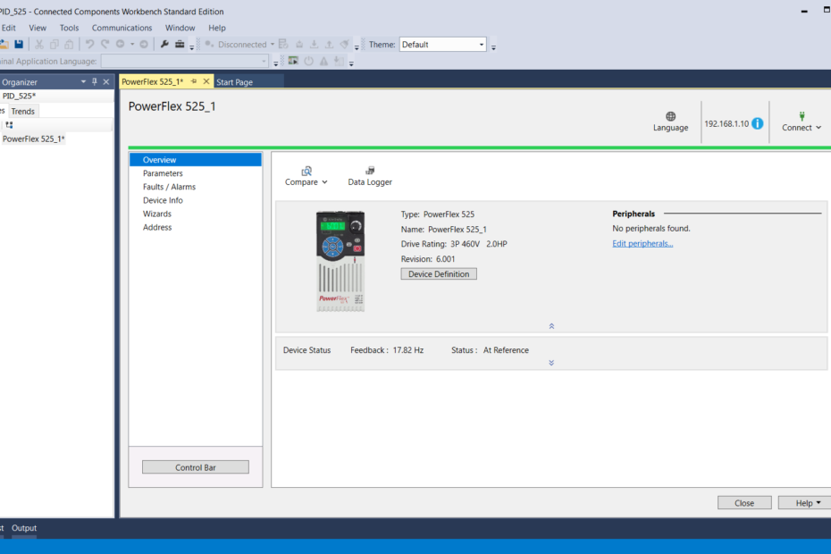
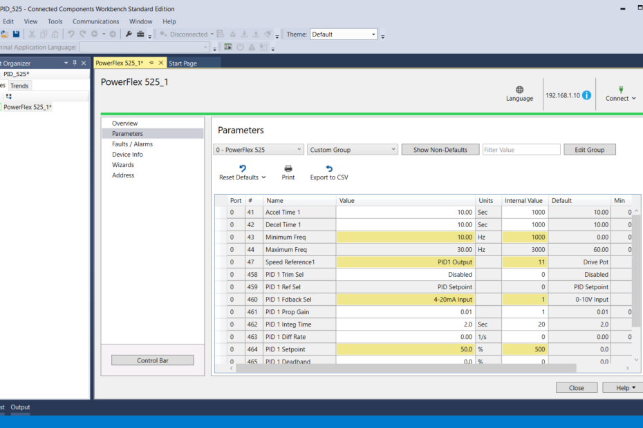
Open ‘Connected Component Workbench’ Software ( free download from Rockwell website) & connect with Powerflex 525 Drive.
Set the following parameters:
P047 [Speed Reference1] = ‘PID1 Output’.
When this is set, it will activate PID control too.
A459 [PID 1 Ref Sel] = ‘PID Setpoint’
A464 [PID 1 Setpoint] set desired Setpoint here.
A460 [PID 1 Fdback Sel] = ‘4-20 mA input’
Leave t095 & t096 [Anlg In4-20mA Low and Hi] to 0 and 100%
A467 [PID 1 Invert Err] depend on PID action
A458 [PID 1 Trim Sel] = ‘Disabled’ to make it Exclusive Control
P041 [Accel Time 1] & P042 [Decel Time 1] Set initially 5-10 seconds
A faster response PID gain, need accel and decel times to be shorter to match the speed of corrections.
P044 [Maximum Frequency] Set it to achieve the desired setpoint without causing instability. Start with 50-60 Hz
P043 [Minimum Frequency] Set it high enough to maintain process stability & prevent motor stalling. Set initially at 20-25 Hz
A461 [PID 1 Prop Gain] or Kp. It can cause instability if set too high.
A462 [PID 1 Integ Time] or Ki. It help eliminate steady-state errors.
A463 [PID 1 Diff Rate] or Kd. To much Kd can cause system overly sensitive to noise.
You can set Kp, Ki and Kd to default value first.
A465 [PID 1 Deadband] & A466 [PID 1 Preload]. Set it to default or per desired.
That’s it.