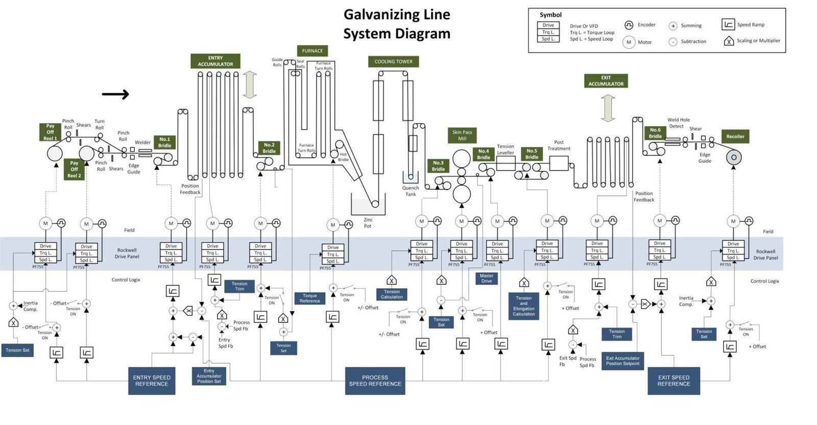
This is 𝗚𝗮𝗹𝘃𝗮𝗻𝗶𝘇𝗶𝗻𝗴 𝗟𝗶𝗻𝗲 System diagram. It shows an overview of speed control and tension control beside the process line.
What is system diagram?
𝗦𝘆𝘀𝘁𝗲𝗺 𝗱𝗶𝗮𝗴𝗿𝗮𝗺 is used to show simple high level view of control of machine. It shows physical relation and interaction between process equipments and control devices. It help to get a clear, complete, common understanding of the system.
System diagram usually created before the machine was build . Since diagram shows the whole picture of the system , it is quite useful for troubleshooting the machine.
Example : One of process section seems to have intermittent problem and faulted on overload. We can immediately think that, the problem should be there too. But that is not always true. It can be caused by other sections due to interaction from other process.
Sure this misdiagnosis, can cause longer machine stoppage.
What is Galvanizing Line?
𝗚𝗮𝗹𝘃𝗮𝗻𝗶𝘇𝗶𝗻𝗴 𝗟𝗶𝗻𝗲 is a production line or machine that used to cover metal sheet with coating of zinc to protect it from rust. As this line runs continously, it also called Continous Galvanizing Line ( CGL). Other name, could be Metal Coating Line which combination of Galvanizing Line and Chemical Coating Line.
What drive controlled main component on this machine?
𝗣𝗮𝘆 𝗢𝗳𝗳 𝗥𝗲𝗲𝗹 / 𝗨𝗻𝘄𝗶𝗻𝗱 / 𝗗𝗲𝗰𝗼𝗶𝗹𝗲𝗿
Used to unwind the coil with steady tension and to feed the production line.
𝗕𝗿𝗶𝗱𝗹𝗲
Used to increase or decrease and isolate tension of next section to previous section. Bridle is used, since each process section in Galvanizing line need different tension requirement.
𝗦𝗸𝗶𝗻 𝗣𝗮𝘀𝘀 𝗠𝗶𝗹𝗹 𝗮𝗻𝗱 𝗧𝗲𝗻𝘀𝗶𝗼𝗻 𝗟𝗲𝘃𝗲𝗹𝗲𝗿
Used to flatten the metal sheet to get desired flatness and surface finish.
In Tension Leveler , metal strip is leveled using combination of tension generated by bridle rolls and by bending strips over several small diameter rolls.
𝗘𝗻𝘁𝗿𝘆 / 𝗘𝘅𝗶𝘁 𝗔𝗰𝗰𝘂𝗺𝘂𝗹𝗮𝘁𝗼𝗿
Entry Accumulator is used to accumulate web material to ensure constant speed on process line, during exchange of coil on unwinder / Pay Off Reel.
While Exit Accumulator is used to accumulate web material during removal of finished coil at Recoiler on exit section.
To ensure continous production process and minimal downtime, Entry Accumulator standby in full storage condition, while exit Acummulator in near empty condition.
𝗥𝗲𝗰𝗼𝗶𝗹𝗲𝗿 / 𝗥𝗲𝘄𝗶𝗻𝗱
Used to wind the metal sheet into the coil with steady tension after it has been processed in the production line.
Note:
For simplicity, some sensors, instruments, motor, drives and several details are not shown on this system diagram. Eg. Load shared slave drive for Bridle, furnace roll etc.