Yes, It can.
Induction or asynchronous motor, not only can be controlled by AC Drives but also by Servo Drives, such as Allen-Bradley Kinetix 5700 & 5300 for Positioning Applications.
Having a Servo Motor breakdown & no spare? Well, one option that can be considered is to replace it with Induction Motor.
When to use AC Induction Motor instead Servo?
✅️ In Positioning Applications where precise positioning & fast dynamic response are not critical (e.g. Conveyor system).
✅️ Reduce Cost. Servo Motors are more expensive than AC Induction Motors especially for higher KW.
✅️ High Inertia & Power Servo Application (e.g. Material Handling). Since Induction motor can has larger rotor Inertia & power
What is the Difference?
◾️ Induction Motor Precision & Response times are less (since use electromagnetic induction) than a servo motor.
◾️ Induction motors are bigger for the same KW. So check the space for it.
◾️ Permanent magnet Servo motors are more energy efficient because not require energy to induce a magnetic field.
Verify Servo Drive current rating , Fuse, MCCB etc
◾️ Induction motors has larger rotor inertia. Consider current rating, acceleration & deceleration time.
What is the required Hardware?
1️⃣ AC Induction Motor.
2️⃣ Induction Motor compatible Servo Drive(Kinetix 5300, 5700).
3️⃣ Ethernet Card such as ENxT Card, or Processor embedded Ethernet.
4️⃣ PLC that support CIP Motion (For Compact Logix use part no. with letter M).
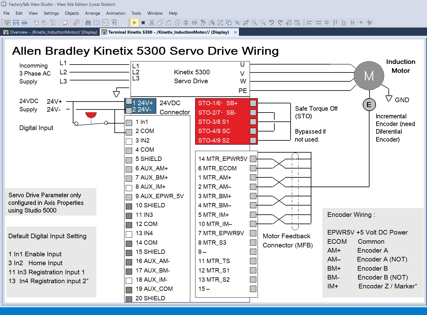
5️⃣ Motor with feedback. For incremental encoder, need differential type.
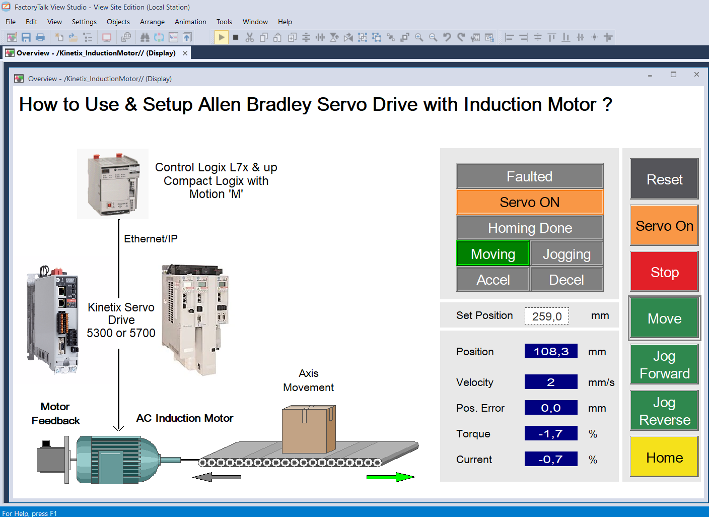
Here’s how to setup it on Kinetix 5300 Servo Drive:
◾️ Set Servo Drive IP Address.
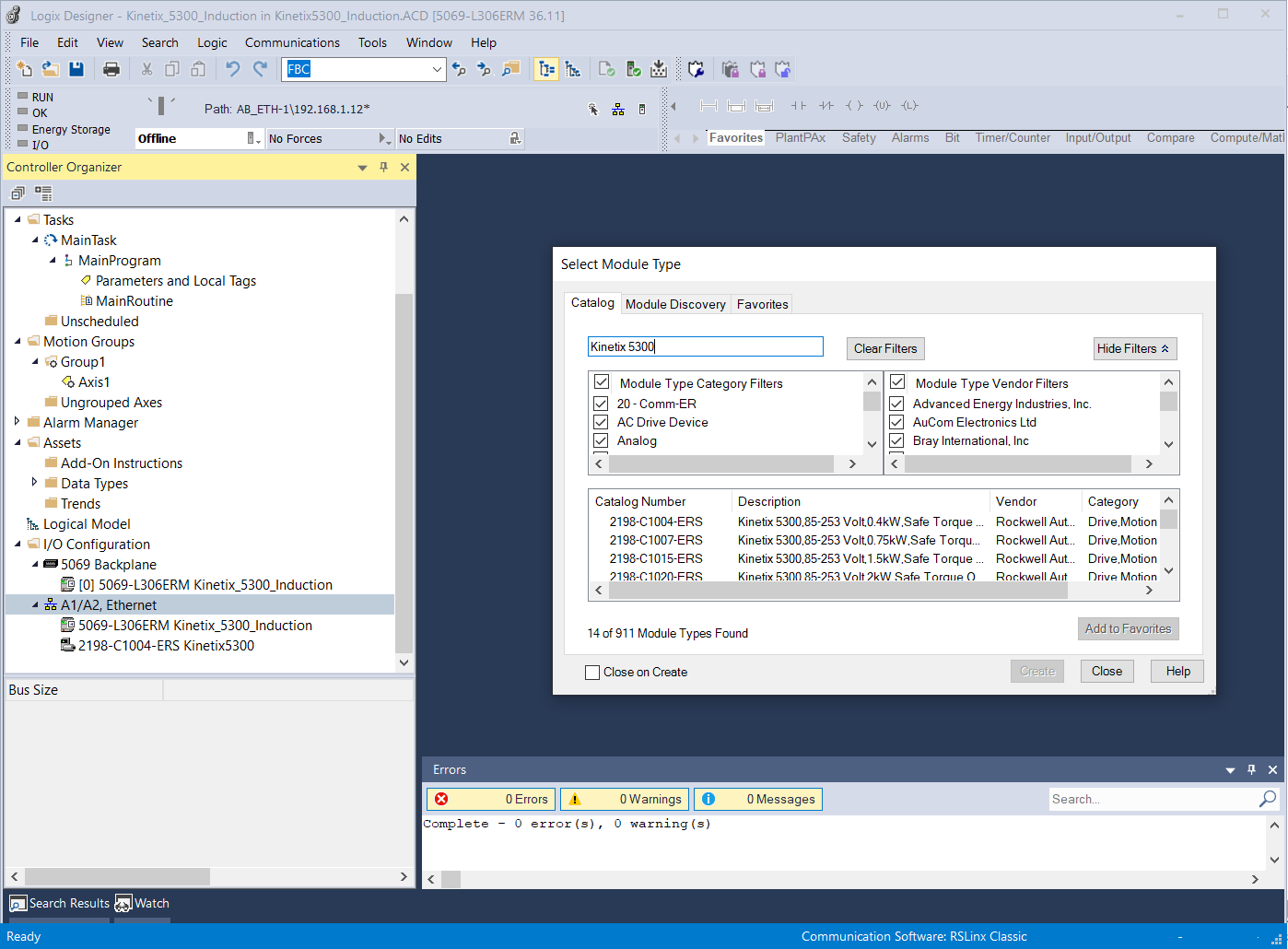
◾️ In Studio 5000 In I/O Configuration,
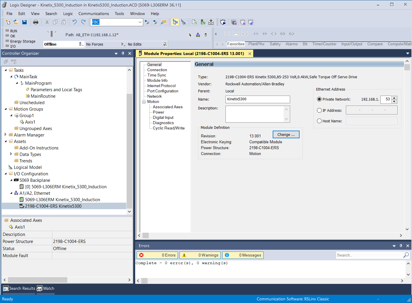
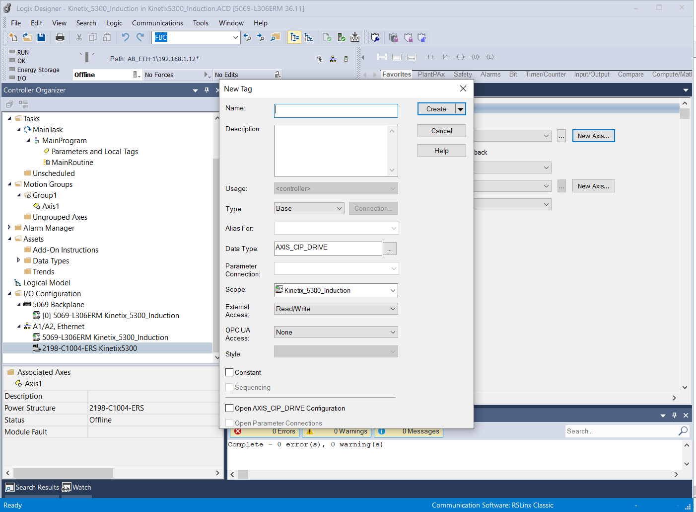
– Create New Module using ‘Kinetix 5300’ & give name.
– Key in IP address in General Tab. Click OK.
– Set Revision
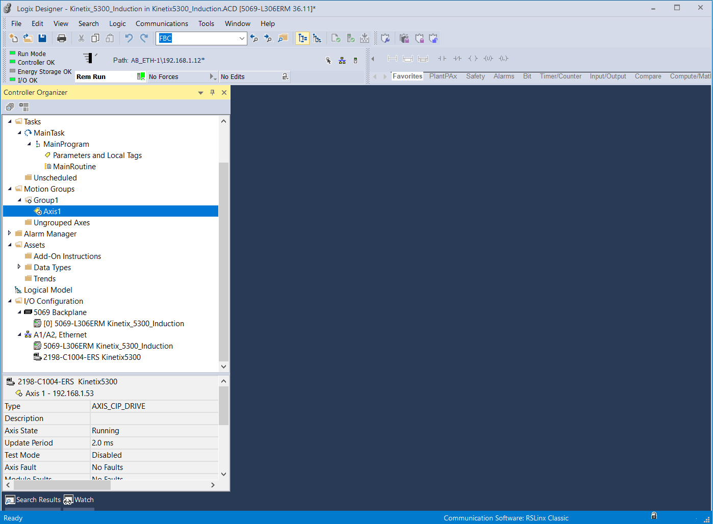
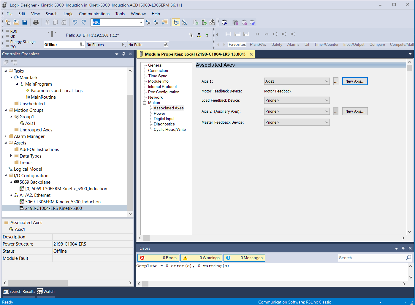
– Create New Axis & assign New Axis to Axis 1 in Assosiated Axes Tab
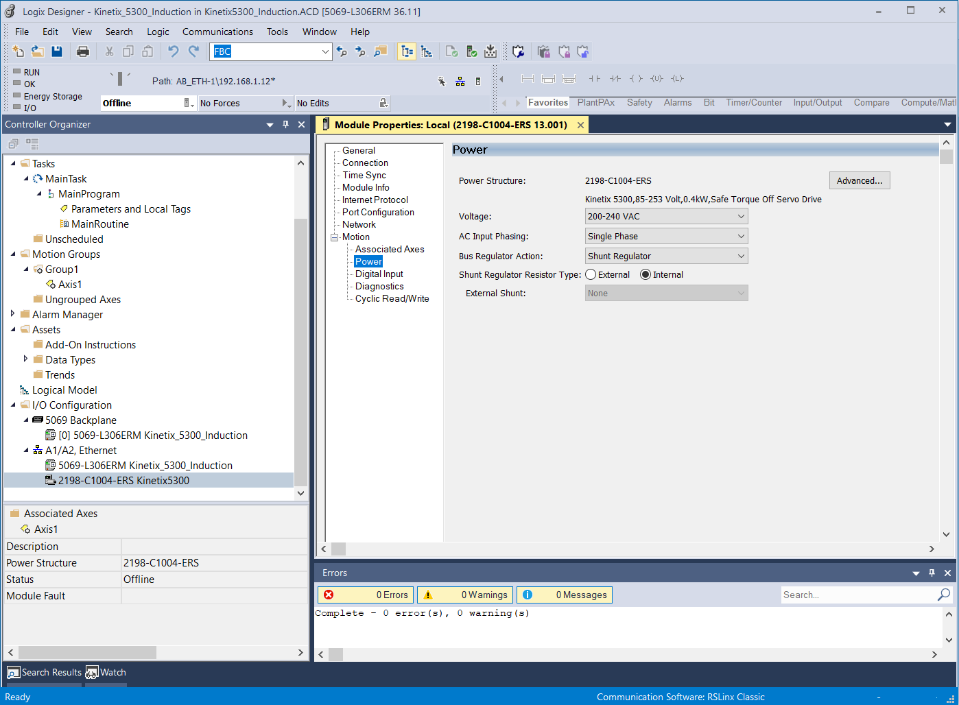
– Set configuration in Power Tab
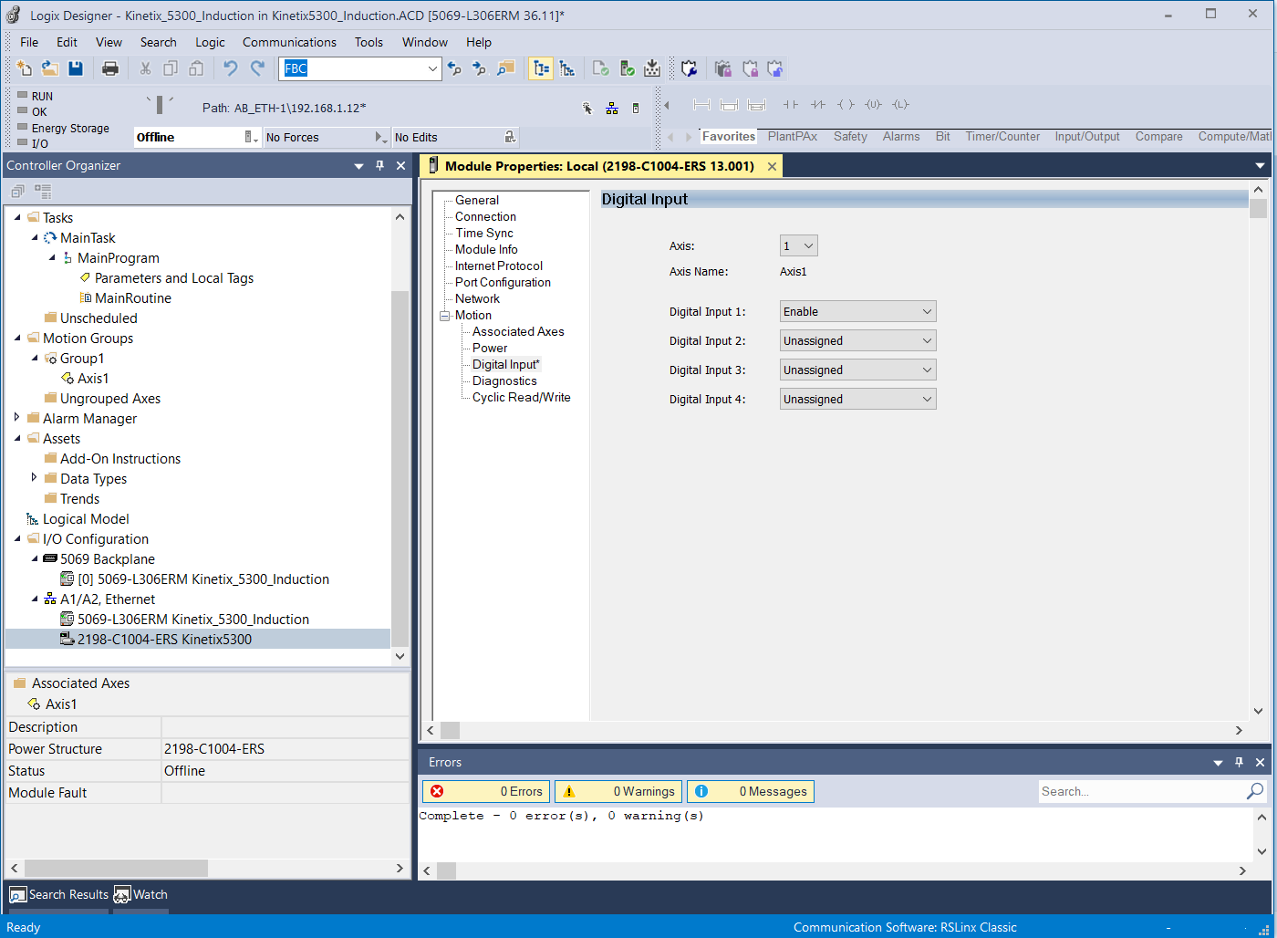
– Assign Enable Input at Digital Input Tab. Click OK.
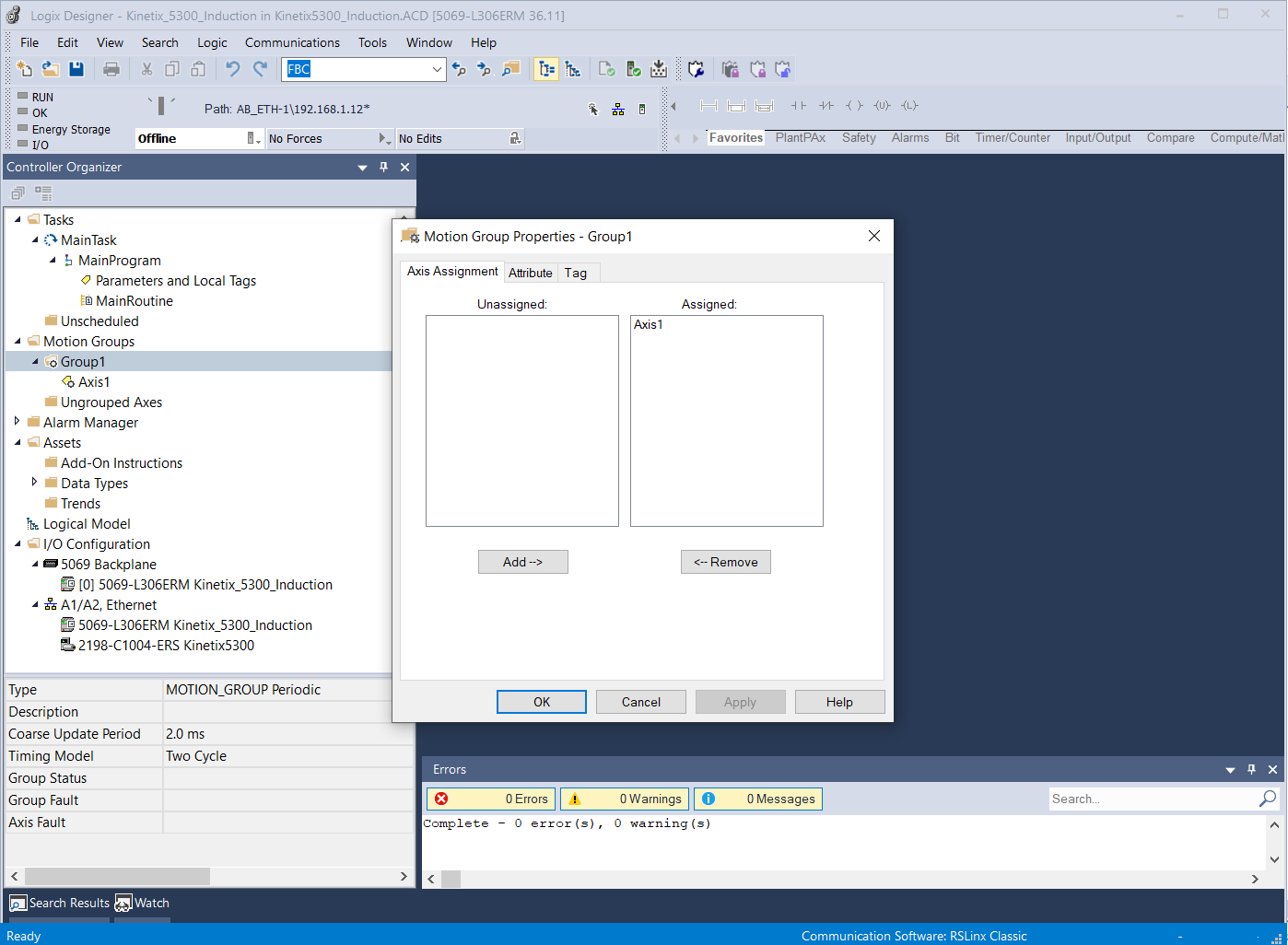
◾️ Create Group & Assign Axis to the Group.
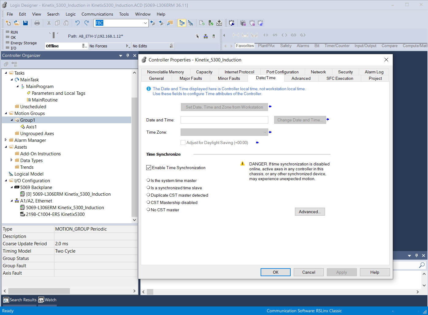
◾️ Enable Time Synchronization in the Controller properties – Date/Time dialog box
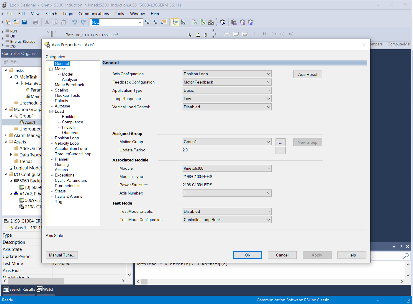
◾️ Set Axis Properties:
– Set Axis Configuration as ‘Position Loop’.
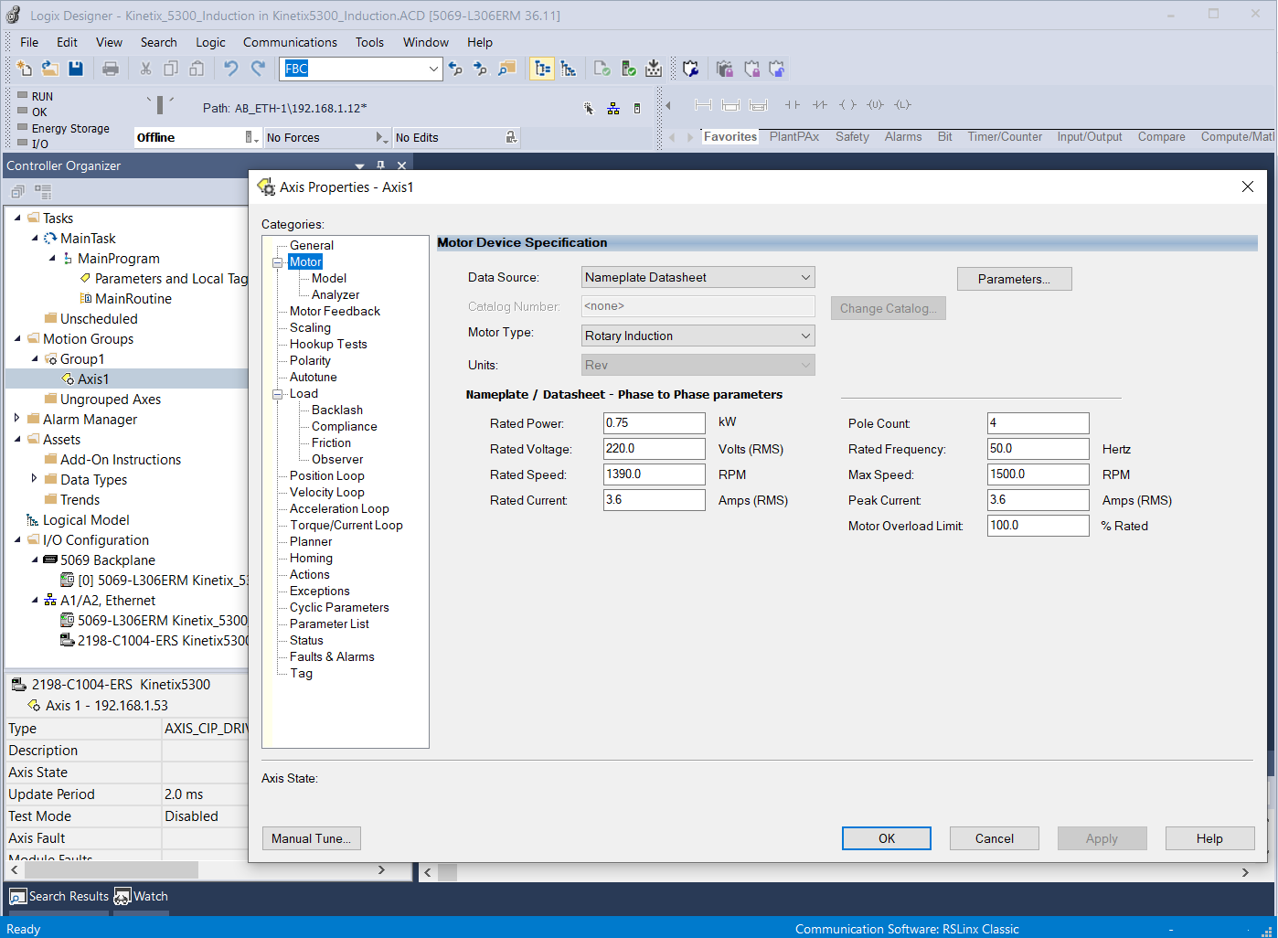
– In Motor Tab, set Data Source as ‘Nameplate Datasheet’. Set Motor Type to ‘Rotary Induction’ & fill in motor data.
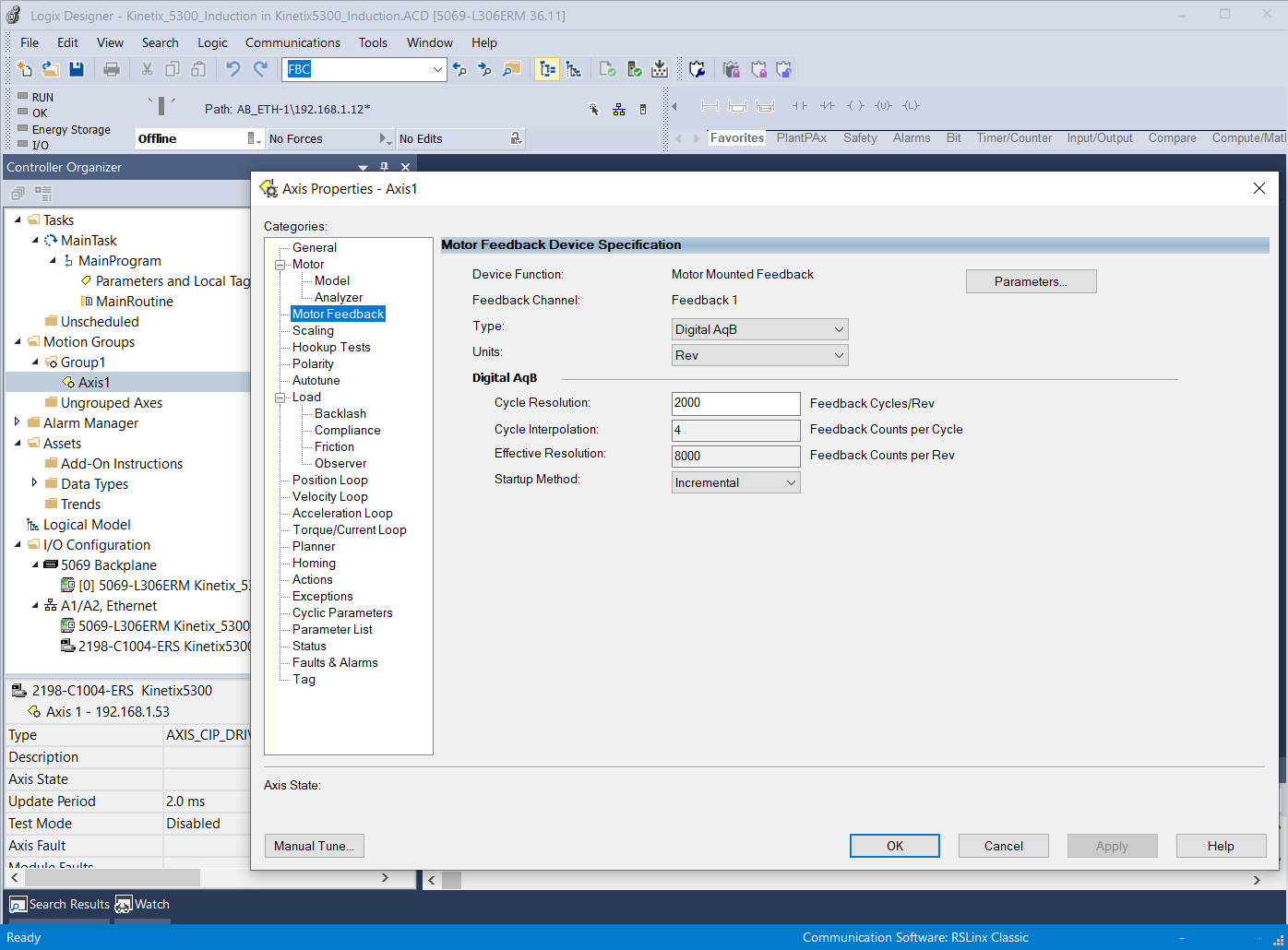
– Setup Motor feedback.
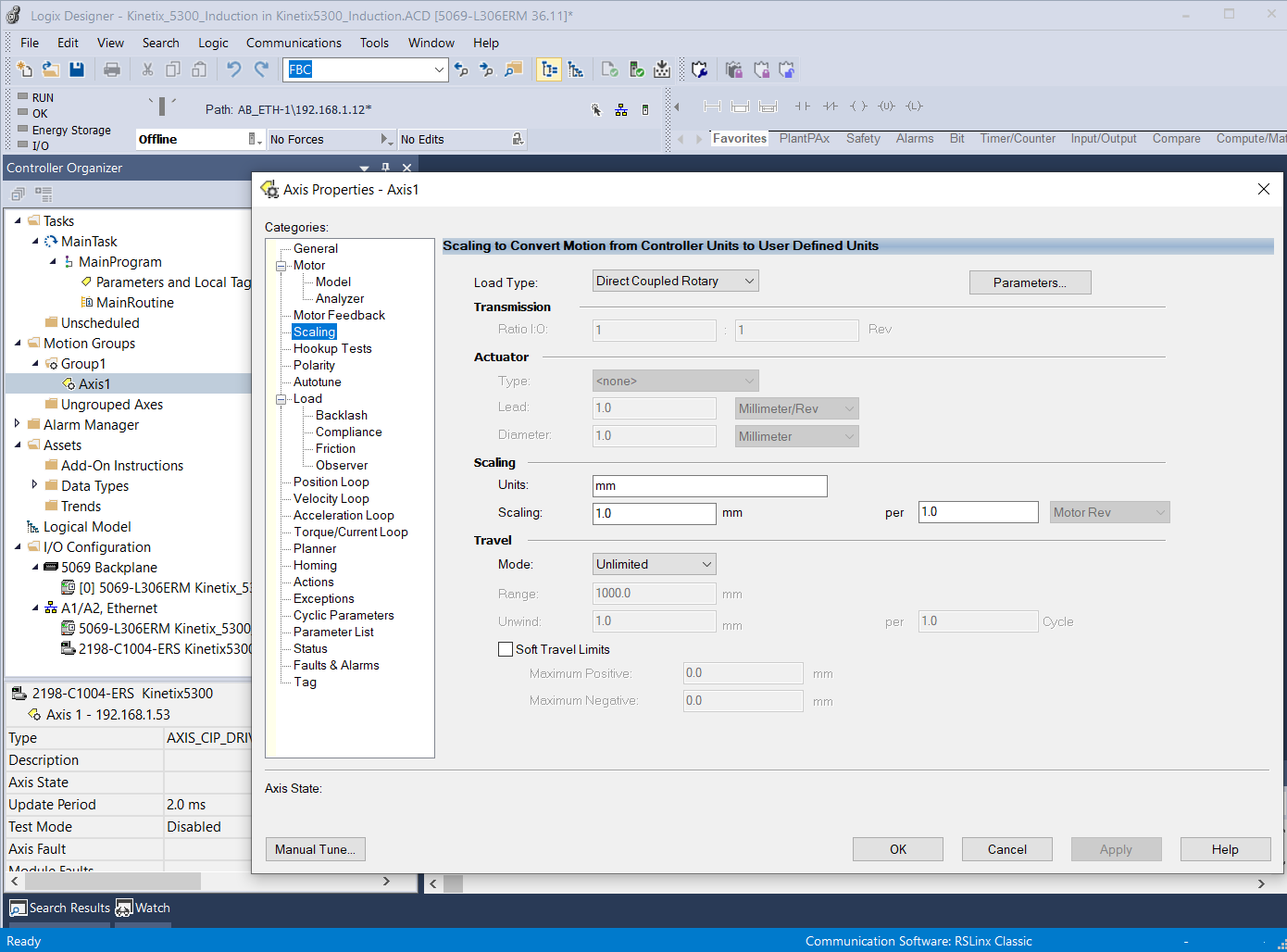
– Enter scaling data.
◾️ Download & Online to PLC
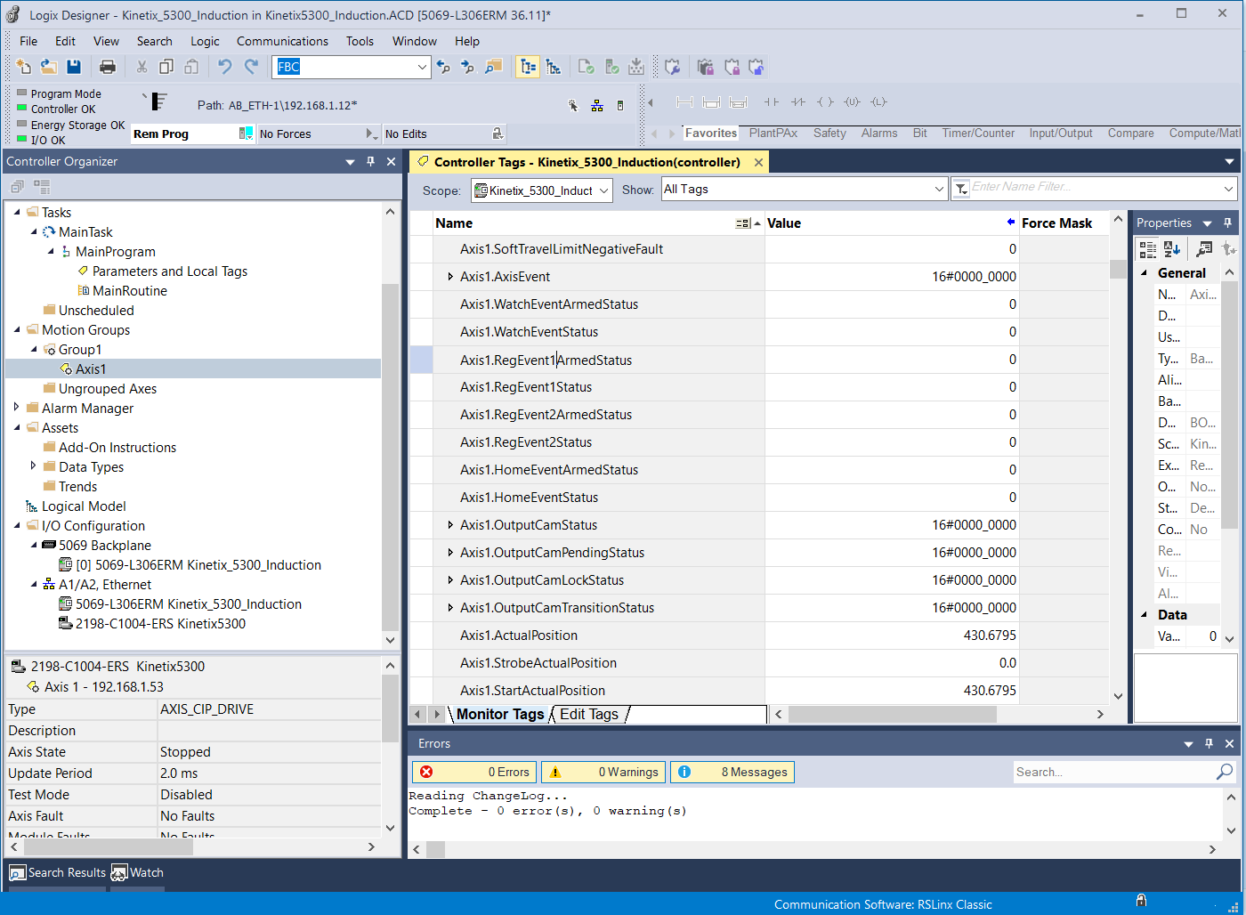
◾️ Verify feedback by rotate motor manually & check Axis1.ActualPosition. Swap Encoder wire if direction is not correct.
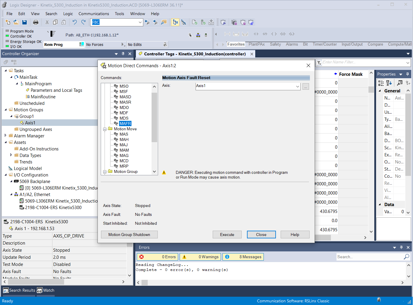
◾️ Reset fault using direct command MAFR (Motion Axis Fault Reset) & close Enable Input
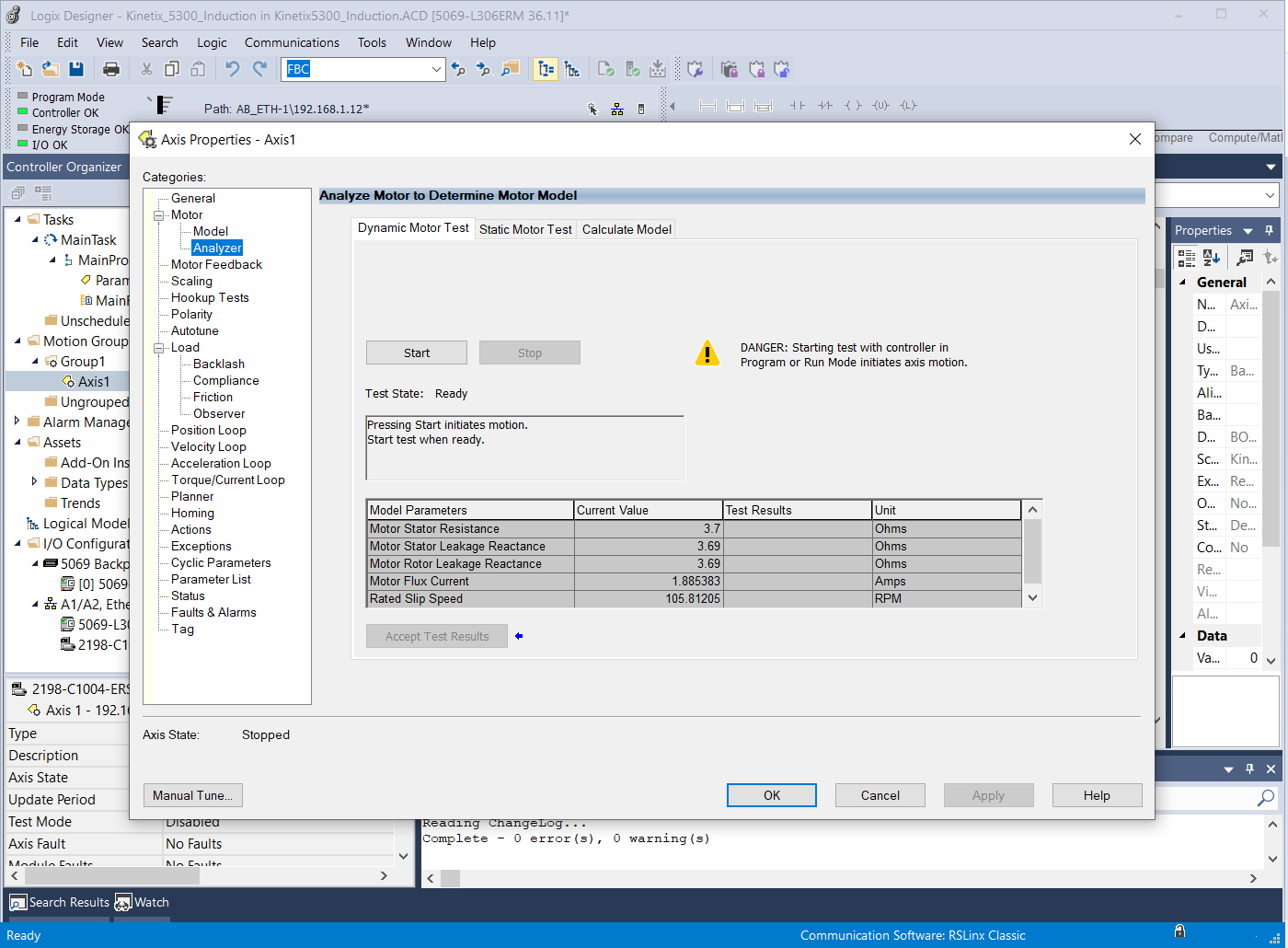
◾️ Use Dynamic Motor Test in Analyzer Tab to check the motor rotation. Swap Motor lead if the direction is not correct
◾️ Encoder & Motor direction can be set from configuration on Polarity Tab in Axis properties
◾️ Program Motion Instruction & run the program.
That’s it. Any plan to use Induction Motor in Motion Control application?