In Positioning Applications requiring high power, where precise positioning and fast dynamic response are not critical,
AC drive system can indeed offer advantages over Servo Drive Systems.
Here’s why:
▪️ Lower Cost. As power requirements increase, Standard Servo systems are typically more expensive than AC Drive systems.
▪️ In many High-Power Servo application, the focus is on handling heavy loads efficiently & safely, rather than on speed and agility.
▪️ AC Drive offers:
* Easier maintenance & Installation.
* Easier integration with existing VFD systems.
* Less System Complexity.
What is the difference with Standard Servo System?
▪️Response times & precision less than a true servo system. (eg. 1.5 Degrees accuracy in VFD vs 0.05 Degrees in Servo)
▪️ Limited features.
▪️ Induction motors are bigger for the same KW.
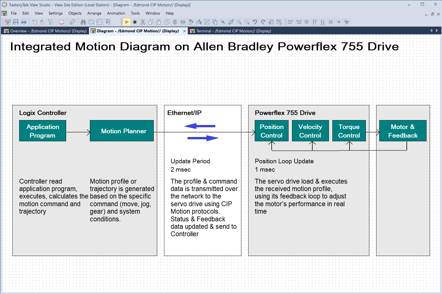
Motion Control application that use AC Drive includes:
▪️ Positioning Large Conveyor Systems.
▪️ Positioning Heavy Material Hoists & Cranes.
▪️ Automated Storage & Retrieval Systems.
▪️ Steel & Metal Processing Lines.
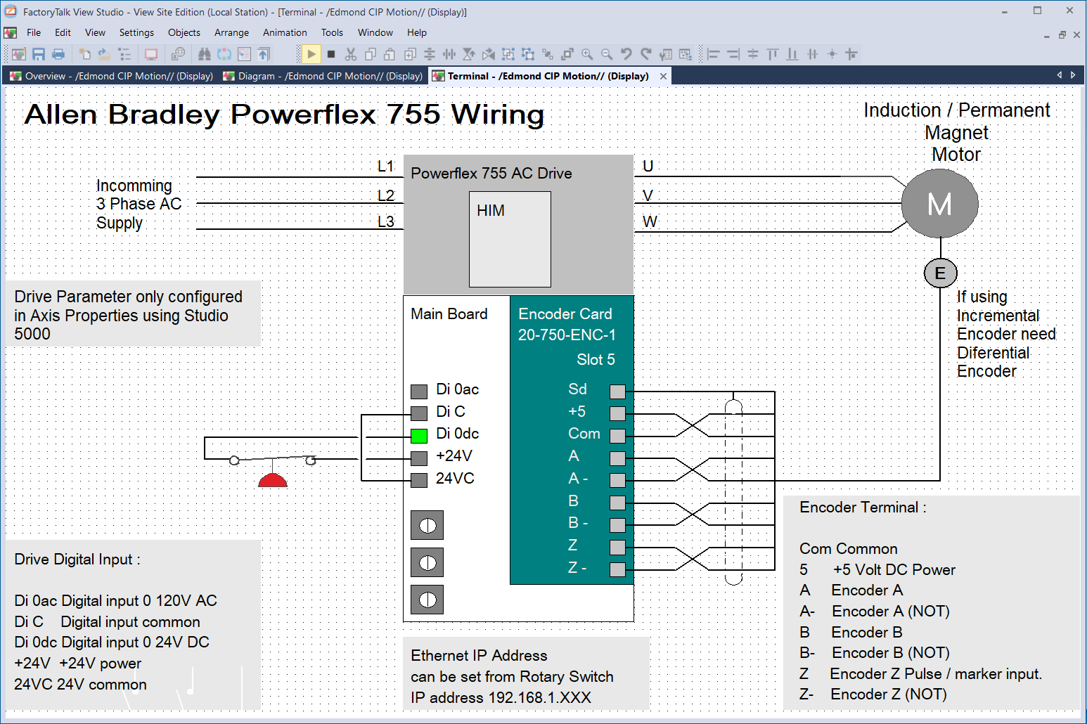
Hardware requirements:
▪️ CIP (Common Industrial Protocol) Motion supported Drive. Such as Powerflex 755 / 755T.
▪️ Drive Feedback / Encoder Card (eg. 20-750-ENC-1)
▪️ Ethernet Card such as ENxT Card, or Processor embedded Ethernet.
▪️ Logix Processor that support CIP Motion (For compact Logix use part no. has letter M).
▪️ Motor with Feedback. For Incremental Encoder, need differential Encoder.
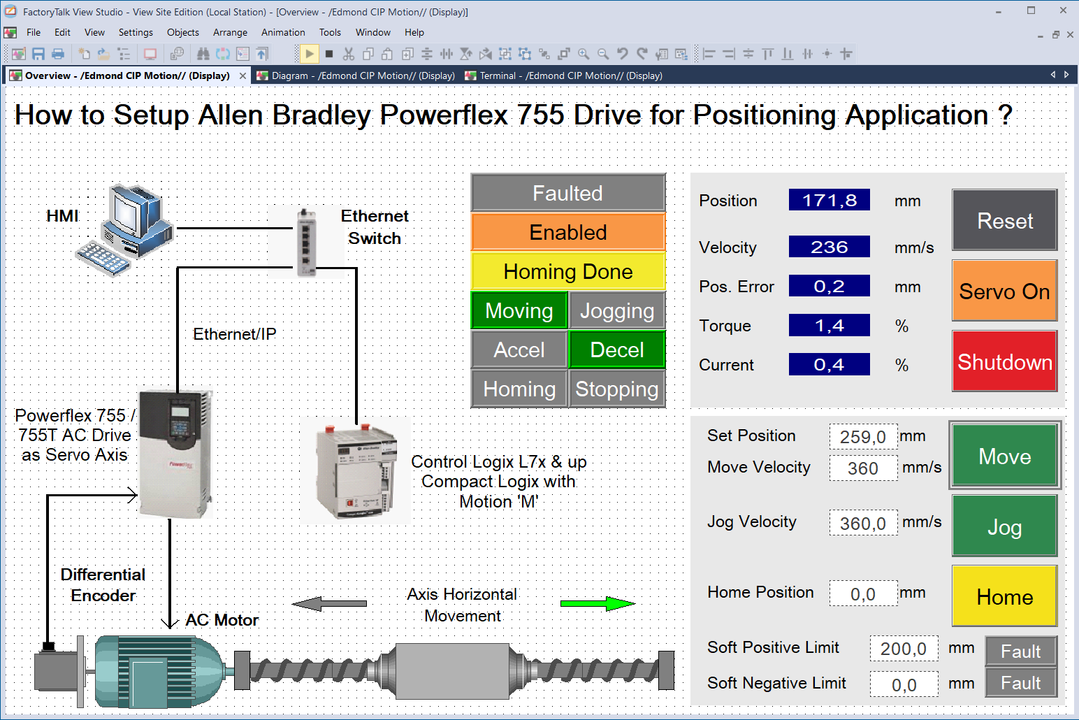
Guidelines on using Powerflex 755 as Servo Axis:
▪️ Safety Card should be in slot 6.
▪️ Digital I/O cards only in slot 7 for Firmware version 12 or higher.
▪️ Use digital input on the main board as an enable.
▪️ For Homming & Registration input, use Universal Feedback Card.
Here’s how:
▪️ Reset Drive to default and Set drive IP Address.
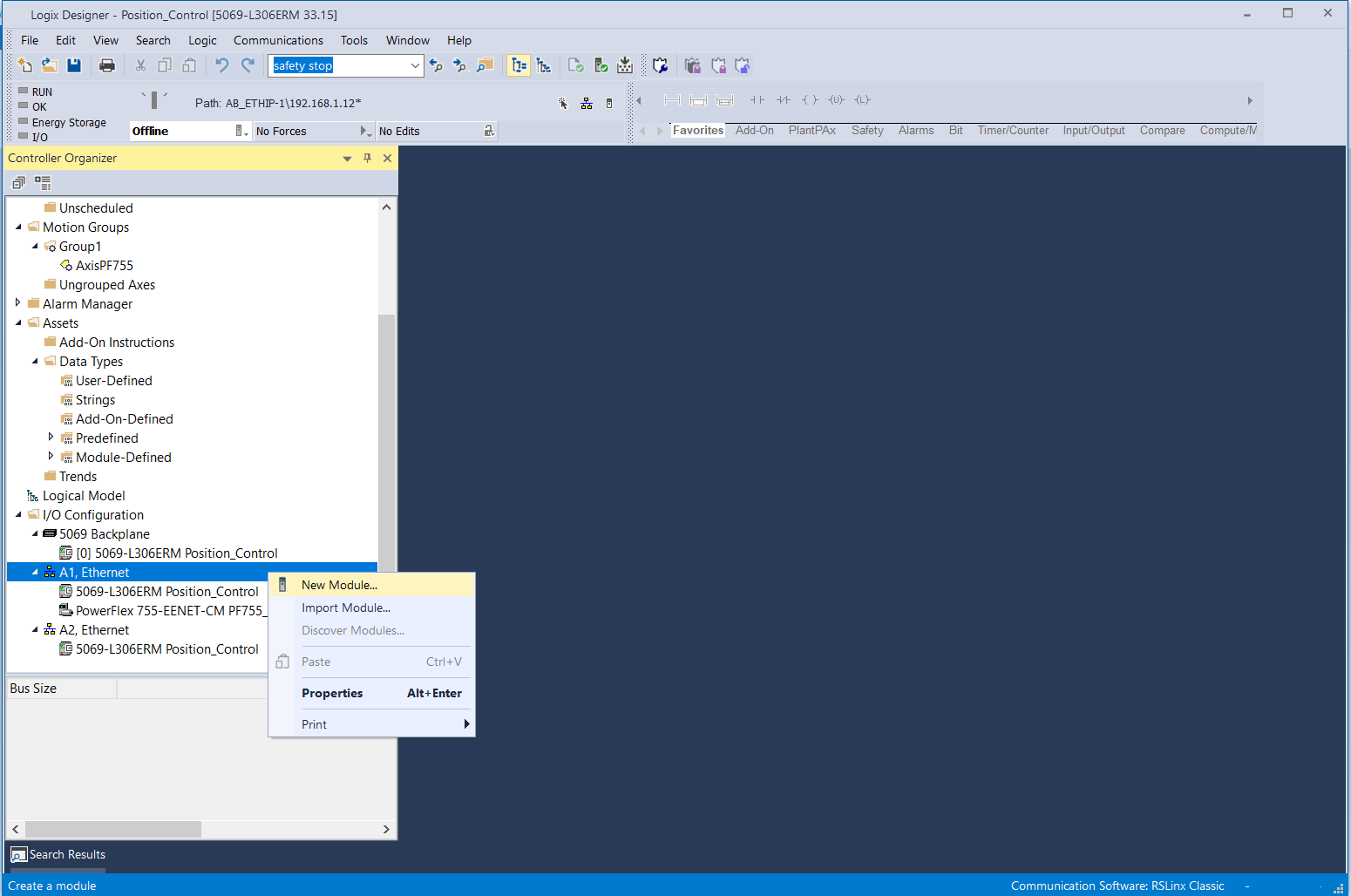
In Studio 5000 program:
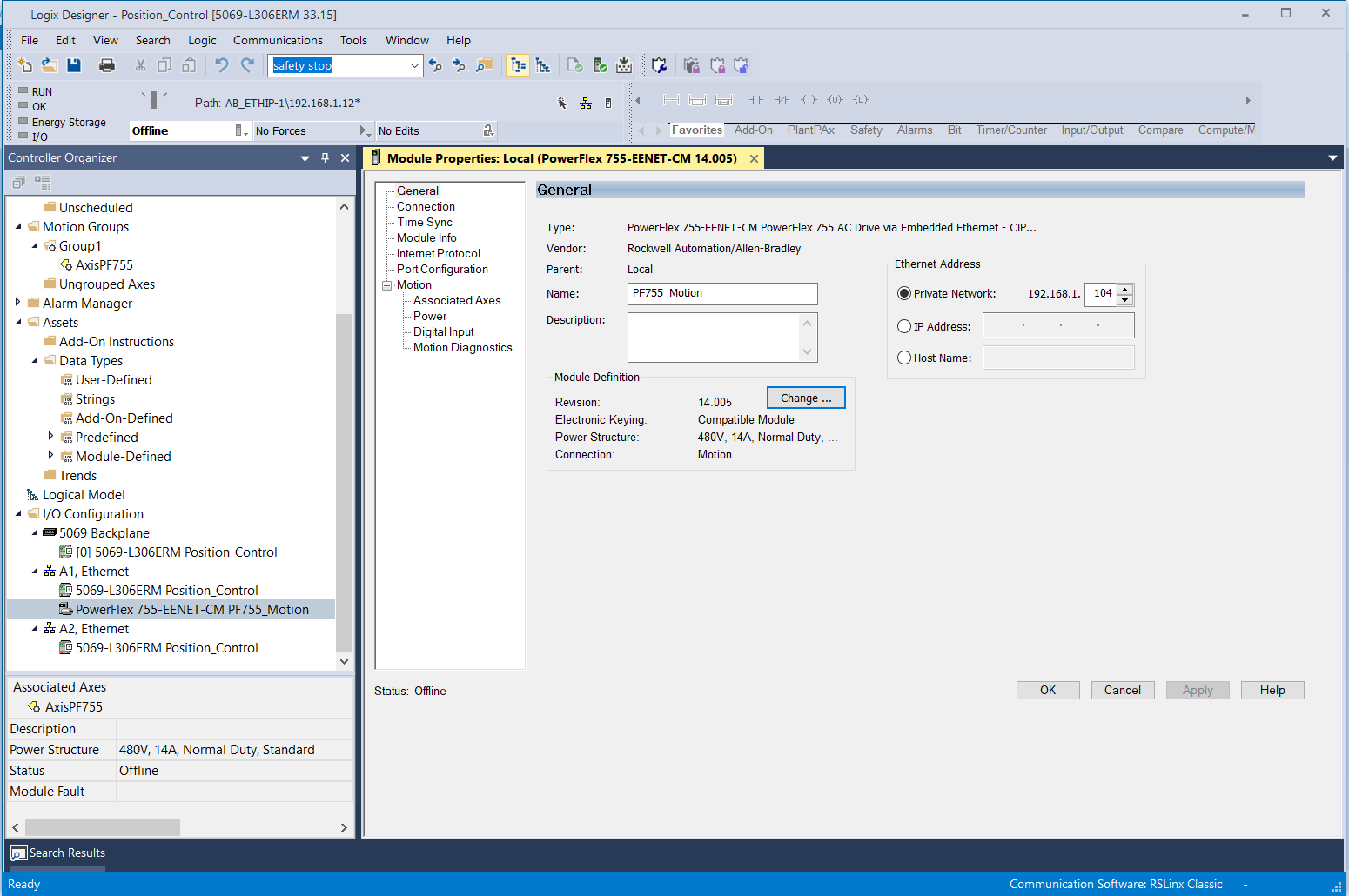
▪️ In I/O Configuration, Create New Module ‘Powerflex 755’ with ‘CM’.
▪️ Put in name & IP address in General Tab. Click OK.
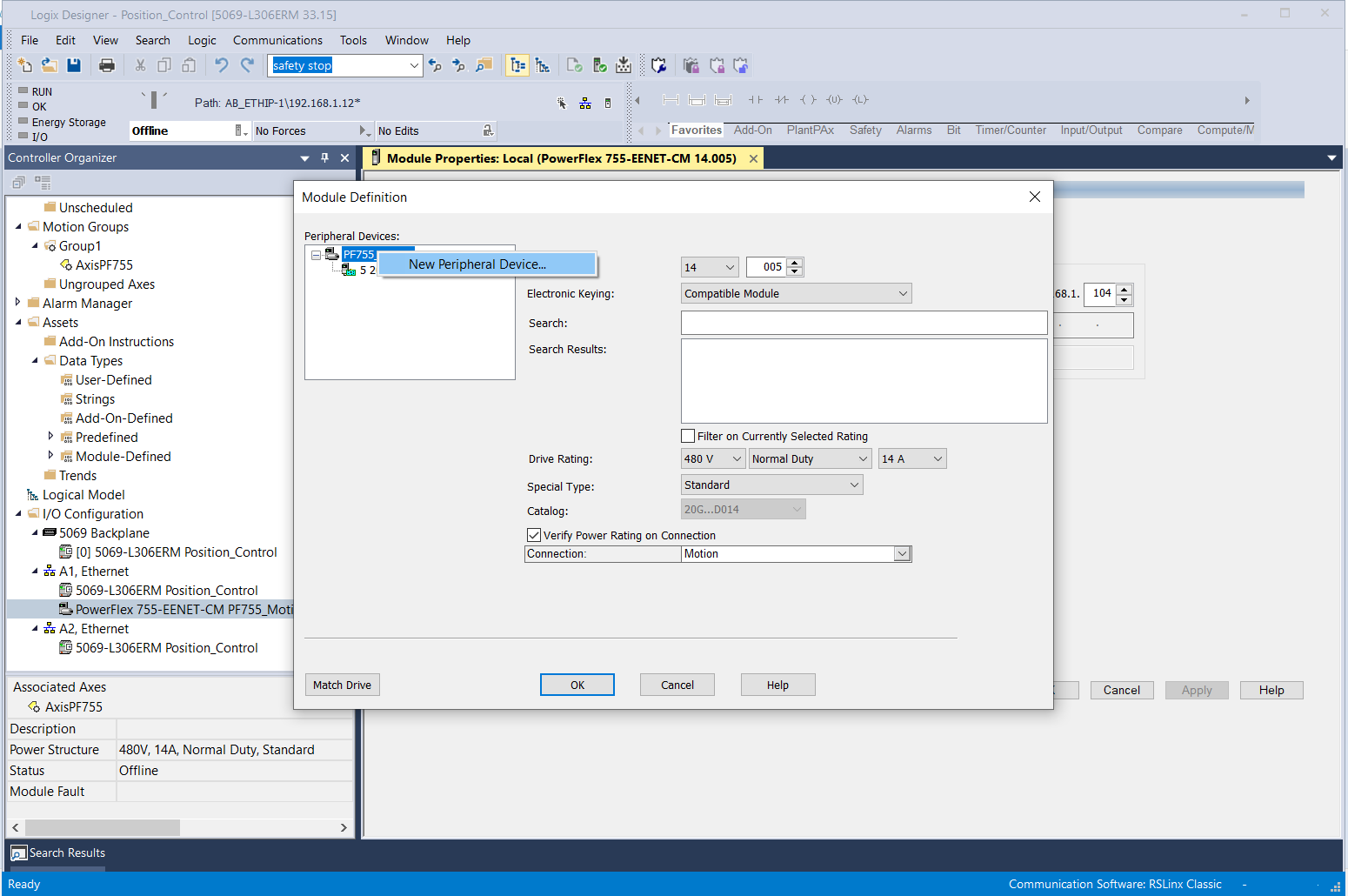
▪️ Set Revision, Drive Rating & add Peripheral like Encoder in Module Definition
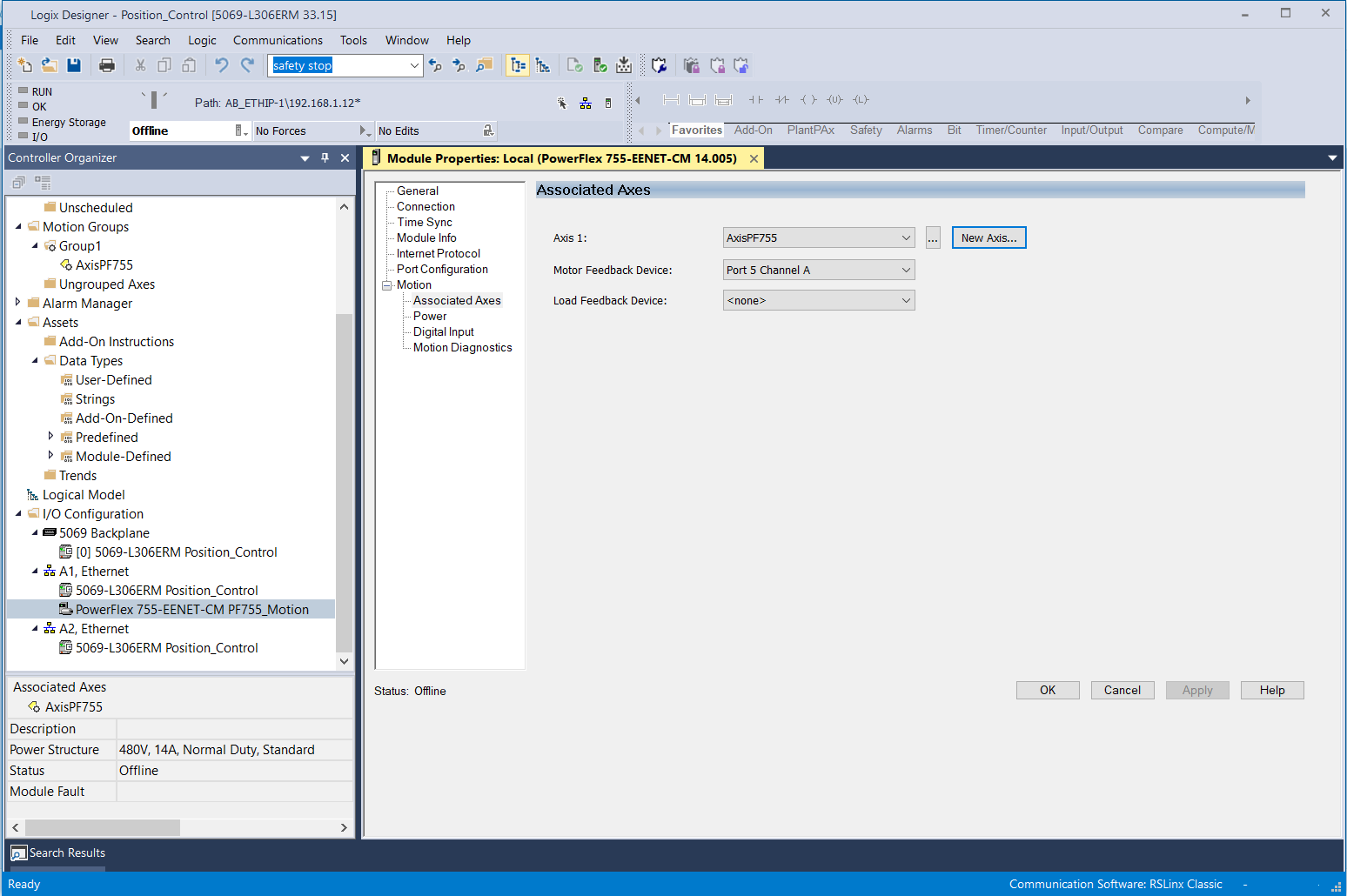
▪️ Create New Axis & assign New Axis to Axis 1 & select Motor Feedback Device in Assosiated Axes Tab
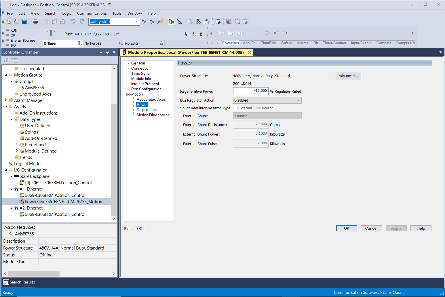
▪️ Set Bus Regulator Action in Power Tab
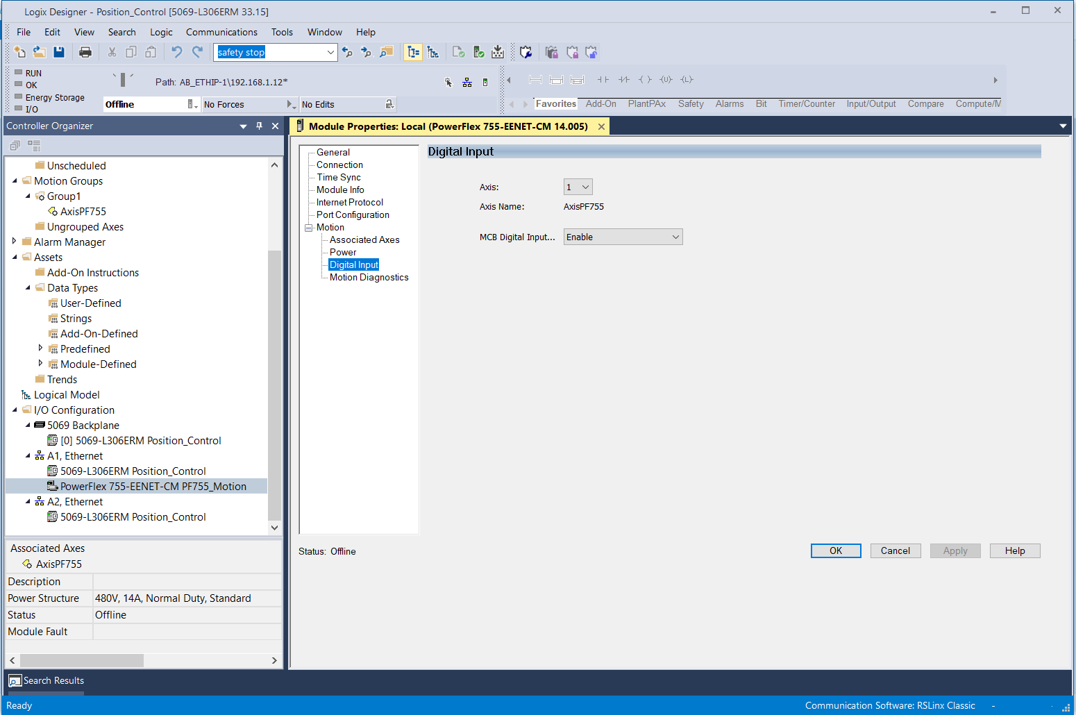
▪️ Assign Enable Input at Digital Input Tab. Click OK.
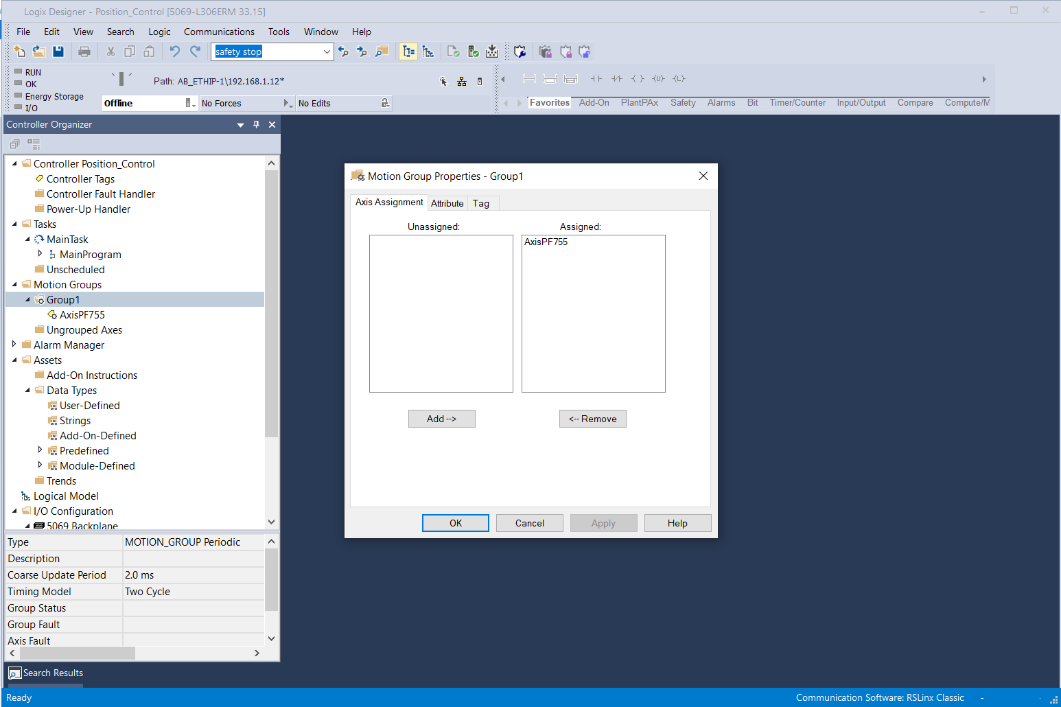
▪️ Create Group & Assign Axis to the Group.
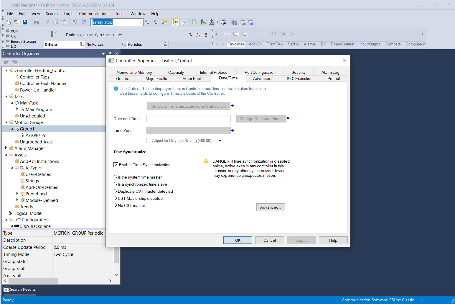
▪️ Enable Time Synchronization in the controller properties – Date/Time dialog box
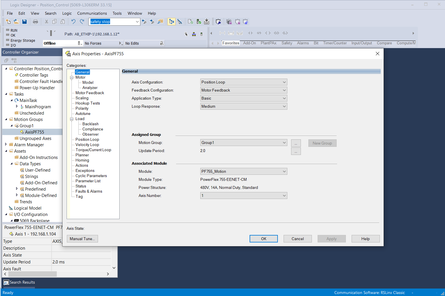
▪️ Set Axis Properties:
* Set Axis Configuration as ‘Position Loop’.
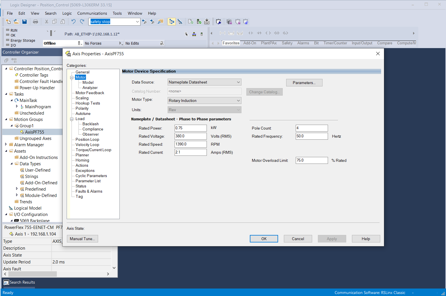
* In Motor Tab, set Data Source as ‘Nameplate Datasheet’. Set Motor Type & data.
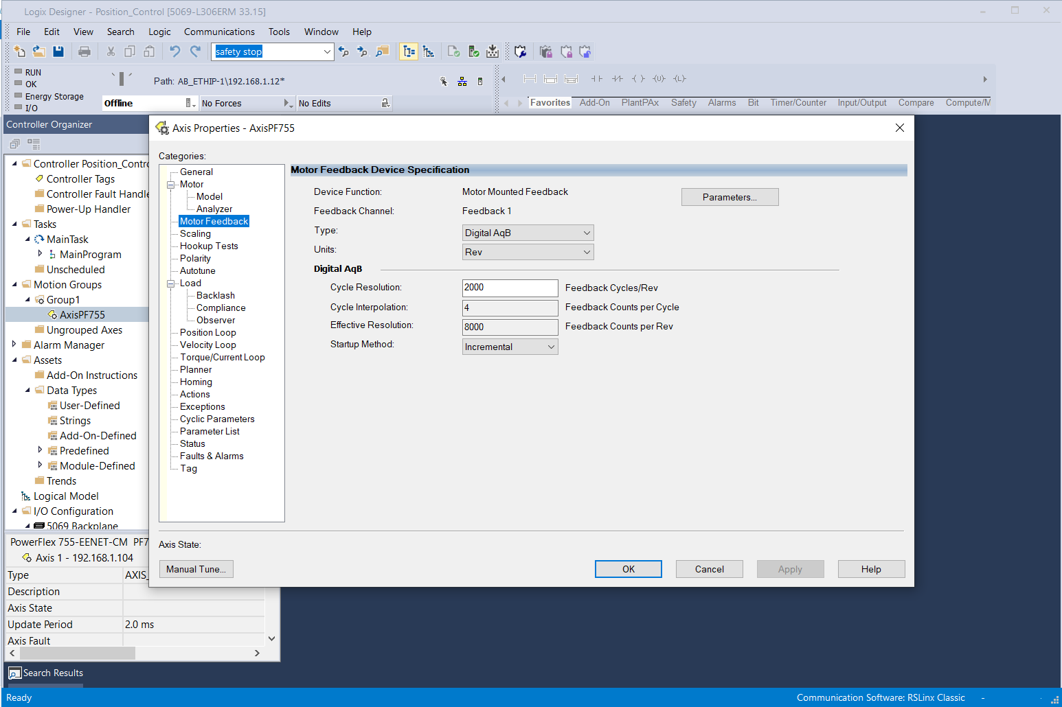
* Setup Motor feedback.
* Enter scaling data.
▪️ Download & Online to PLC
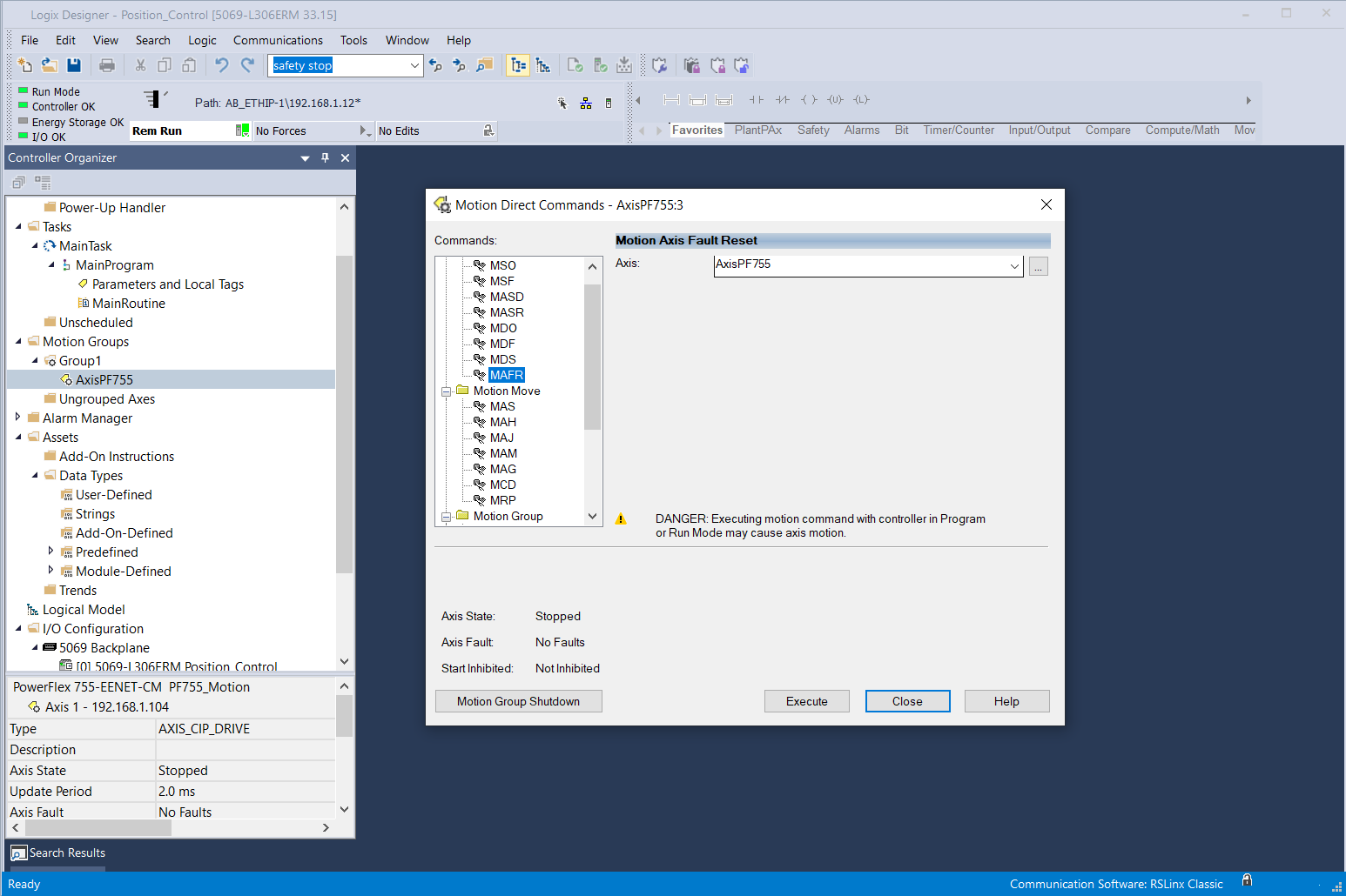
▪️ Close Enable Input and reset fault using direct command MAFR (Motion Axis Fault Reset)
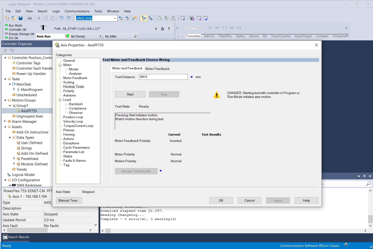
▪️ Do Hook up Test. Accept Test Results.
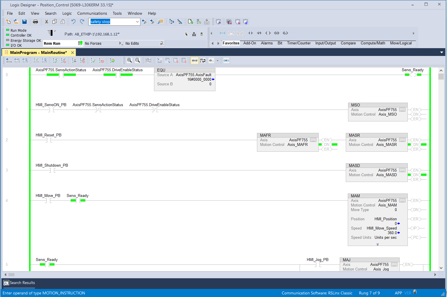
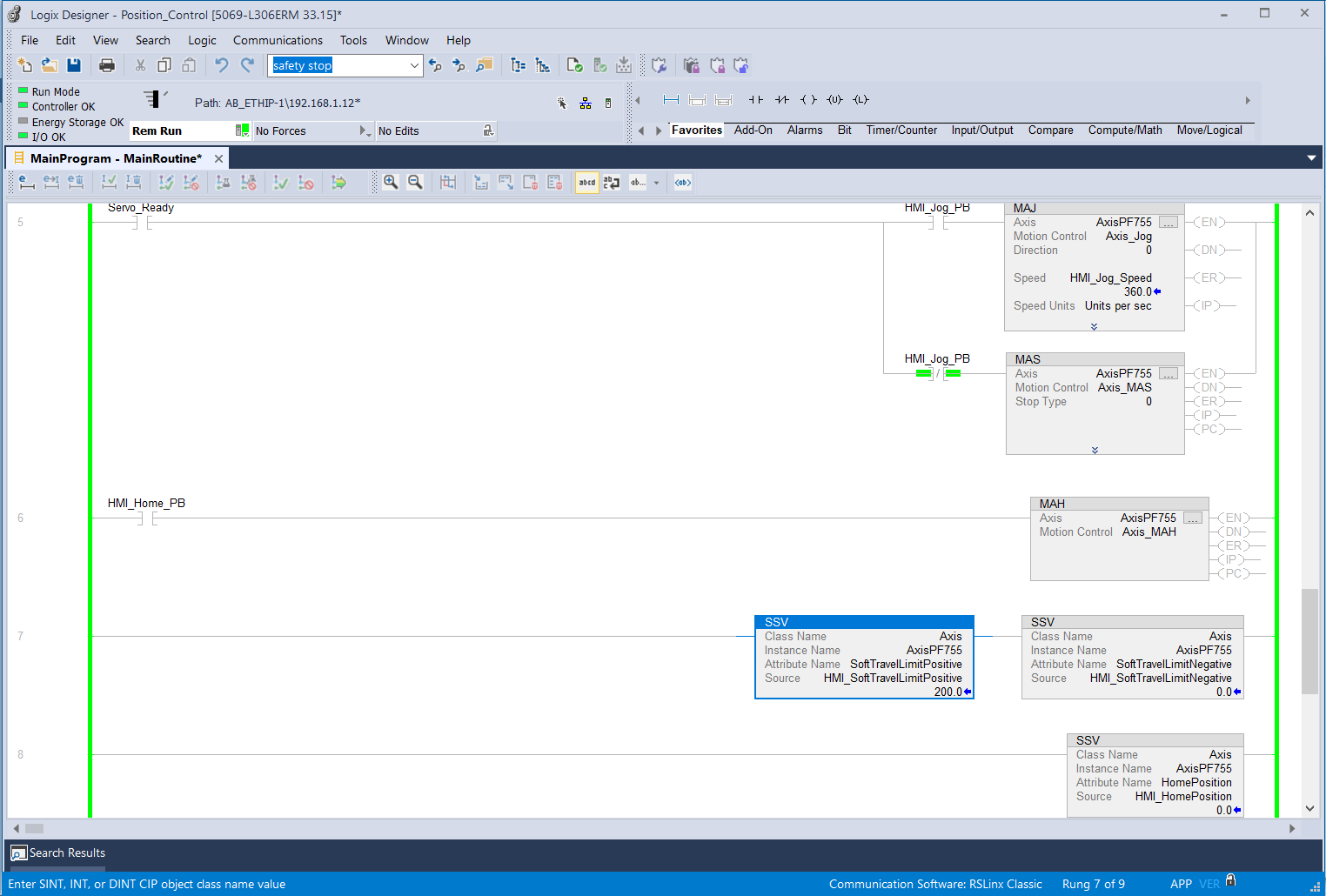
That’s it. It is ready to program using Motion Instruction.
Done.
Have you ever encounter High Power Positioning servo application ?